
APPLICATIONS · EXTERIOR TRIM
Wheel-Arch Trim Tape Bonding: Start With the Joint, Not a Foam Name
Assess wheel-arch tape attachment from the actual substrates, gap and load path.
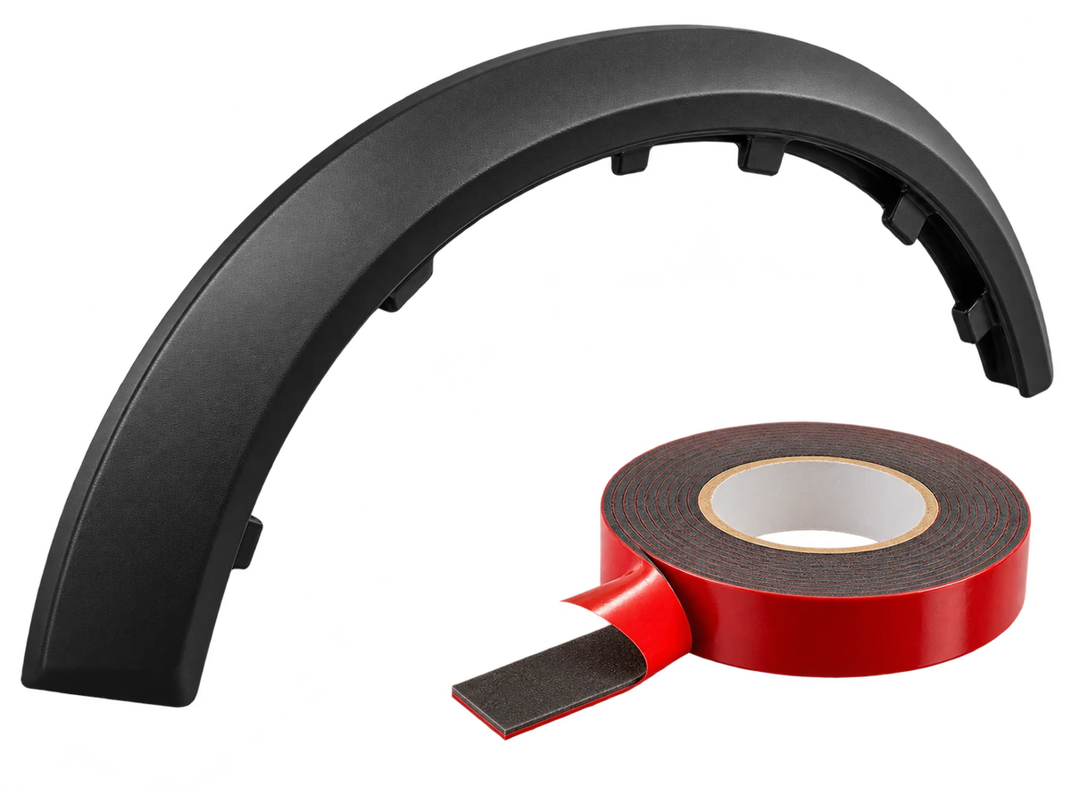
Tape attachment can be a candidate only when the actual plastic and painted surface, trim geometry, contact area and exposure are designed and tested together. Manufacturer wheel-arch examples use dedicated acrylic-foam systems; they do not establish that a generic PE-foam grade or any Broadya model is qualified for this joint.
Start at the two real surfaces
Record the molded resin and additives, paint system, any primer or surface treatment, and production cleaning. PP/TPO parts may present low-energy interfaces; material labels alone do not establish bondability.
Wheel-arch trim is not simply a larger badge. The plastic component may have a low-energy surface, texture, molded-in additive or local treatment; the other adherend may be a particular automotive paint stack. Record both, including the manufacturing route. 3M’s wheel-arch application profile describes a dedicated acrylic-foam attachment approach. That is evidence of an engineered route, not a test result for a Broadya tape or a reason to choose PE foam automatically.
Draw the load path before specifying thickness
Curvature, spring-back, narrow contact and exposed edges can concentrate peel stress; evaluate the actual part and load path rather than a flat coupon alone.
Map the nominal and worst-case gap along the arch, spring-back force after release from the fixture, contact-band width and the position of clips or other mechanical features. The candidate tape must contact both surfaces while avoiding a peel-prone free edge. 3M’s processing guide explains why: peel stress concentrates at an edge, unlike a distributed shear load. Increasing foam thickness without fixing the load path may leave the failure unchanged.
Validate the assembly that will ship
Trial production-molded trim and production-painted panels with the intended cleaning, treatment, pressure and dwell. Inspect coverage and edge contact before environmental exposure. Then use the OEM’s actual water, temperature, cycling and mechanical criteria. The 3M exterior-trim guidelines lists TPO/PP as relevant plastic substrates; it does not define acceptance criteria for this project.
The car badge bonding guide addresses a different, smaller exterior joint.
Apply a go/no-go sequence before sampling
Proceed to a tape trial only after surfaces are identified, the land can support the required bond area, and the production process can apply repeatable contact. Use four gates:
1. Surface: identify molded resin, additives and treatment, plus paint system and cleaning process. If either adherend is unknown, hold selection; “plastic to paint” is not enough to choose chemistry.
2. Geometry: map tape-land width, curvature, local gaps, hider lips and edge position on nominal and worst-case parts. If the land is cupped, crowned, contaminated by a gate, or too narrow for placement tolerance, correct the part or process before trial.
3. Load: identify spring-back, opening force and service movement that load an edge in peel. If the design continuously opens the bond, change support or load path before increasing thickness.
4. Qualification: after the first three are controlled, trial a construction documented for the substrates and gap. Use production-representative parts with controlled preparation, pressure and dwell.
A failed gate means redesign or gather missing surface/geometry data. Passing means the project merits a controlled candidate trial; it does not mean the joint is qualified.
Read the tape land and load path together
Mark the tape centerline and placement tolerance on the trim drawing. Confirm that the full tape width stays supported and does not ride onto a lip. Inspect for sink, cup, crown, flash and texture that blocks contact. 3M’s exterior-trim guidelines explain that land width, shape and fit affect performance and that irregularities can prevent wet-out. Apply the principle to the actual part; do not copy a supplier dimension as a Broadya requirement.
Curved trim may spring away from the body panel. Peel stress concentrates near the advancing edge, while supported shear distributes load differently. Record fixture release and part spring-back, then inspect edge contact after application. Thicker foam may accommodate a designed gap, but it does not fix a narrow unsupported land or a force that continuously opens the joint.
Define a passing trial before it starts
Use production-molded trim and production-painted panels, not only flat coupons. Record resin and paint identifiers, cleaner/treatment, application tool, pressure method, dwell before handling and lot. Inspect coverage before environmental tests. Then follow the vehicle program’s water, temperature, humidity, cycling and mechanical requirements. Set acceptance criteria in advance: required coverage, permissible edge lift if any, acceptable failure mode and post-exposure retention. The 3M application example is not an acceptance limit for a Broadya candidate.
The car-badge guide covers a smaller, differently loaded exterior joint; wheel-arch trim needs its own surface and geometry review.
Next step
Share the trim and paint materials, joint drawing, gap map and service test requirement before requesting an attachment-tape evaluation.
Discuss this application
Share the substrate, joint or drawing, service conditions and the decision you need to make.