
BUYER'S GUIDE · PET DOUBLE-SIDED TAPE
PET Double-Sided Tape for LCD Module Assembly: Selection Guide
Select a PET double-sided tape candidate by mapping the bond location and mating materials, defining the assembly gap and tolerances, then validating the construction on the actual LCD module. Catalogue application labels are a starting point, not proof of a specific fit.
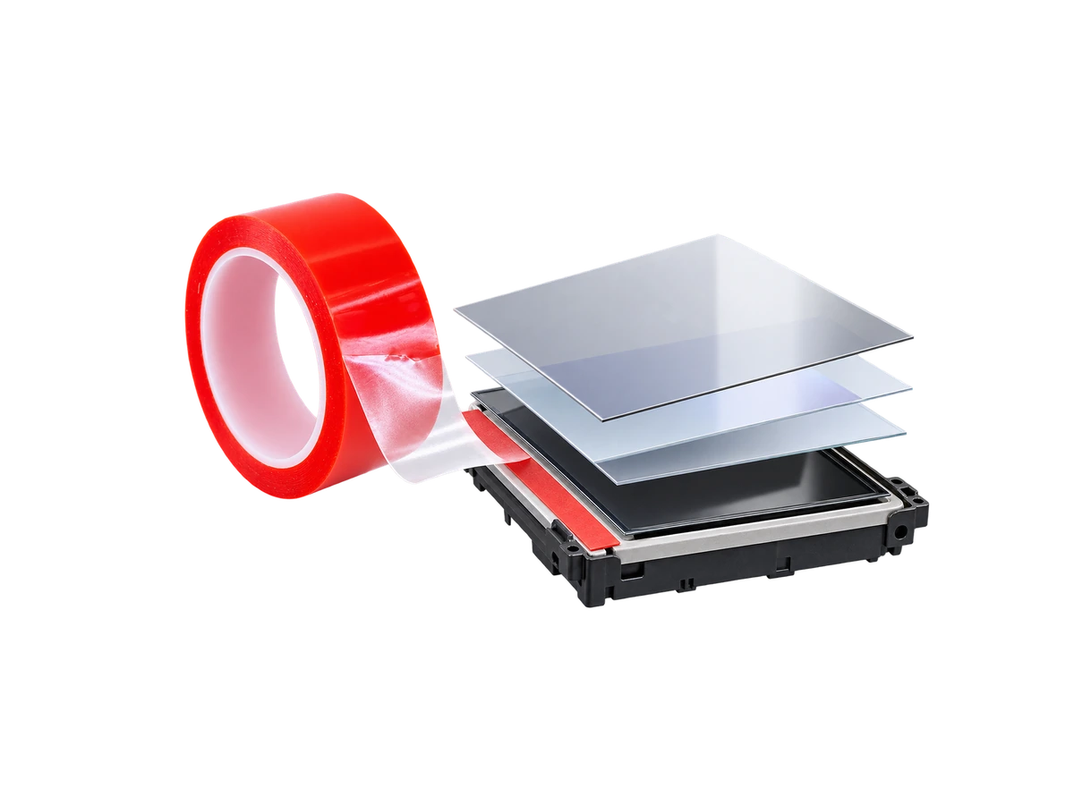
How to select PET double-sided tape for LCD module assembly
Direct answer
Select a candidate PET tape by mapping the bond location and mating materials, defining the available assembly gap and dimensional tolerances, matching the application and supply format to the process, then validating that candidate on the actual assembly. The catalog lists PET double-sided tape in a 30–205 micrometre range and LCD modules as an example application, but it does not confirm a specific construction or fit.
When deciding how to select PET tape for LCD modules, assess one identified candidate against one drawing revision. For PET double sided tape for LCD modules, the LCD module assembly tape application label is a starting point; the interface, dimensions, process and validation record determine what still needs review.
Define the joint and mating surfaces
Specify where the LCD module bonding tape will sit and identify both mating materials, including coatings or surface finishes. Mark the bond outline, available gap, nearby features and areas that must remain clear. If location or materials are missing, complete this interface map before requesting a fit recommendation.
For example, a request for PET tape for LCD frame bonding should identify the exact frame interface and both surfaces. The phrase alone does not establish frame-bonding suitability. Ensure supplier responses and sample records reference the same joint and drawing revision.
For current model range and construction details, see the double-sided PET tape product page; confirm both mating surfaces on the actual assembly drawing.
Separate catalog facts from candidate construction
For PET adhesive tape for LCD assembly, distinguish the product family from the proposed model. Request a construction record before comparing candidates.
| Item | Supplied catalog information | Candidate confirmation needed |
|---|---|---|
| Product family and application | PET double-sided tape; LCD modules are an example application | Model identity and proposed joint |
| Thickness | Family-level 30–205 micrometre range | Available nominal thicknesses, measurement basis and tolerances |
| PET carrier | PET product designation | Carrier specification and thickness |
| Adhesive | No chemistry or side-specific details supplied | Adhesive identification and specification for each side |
| Liner | No construction supplied | Liner material, thickness, release details and removal arrangement |
| Construction identity | No model revision supplied | Model code, construction revision and matching document references |
Record unknown fields as unresolved. Neither the family designation nor the application example supplies bonding strength, temperature resistance, optical performance, residue behavior, compliance or certification.
Match dimensions to the assembly drawing
Choose PET tape thickness for LCD modules through a documented dimensional comparison. A target within 30–205 micrometres still requires model availability, thickness definition, tolerances and dimensional review. The range establishes neither a recommended thickness nor every intermediate size.
| Assembly requirement | Candidate information to request | Review criterion or unresolved issue |
|---|---|---|
| Available gap and its variation | Nominal tape thickness, tolerance and measurement conditions | Compare the documented candidate with the buyer-defined gap limits |
| Thickness definition | Whether reported thickness includes adhesive layers or liner | Compare like-for-like values; identify what remains in the assembled joint |
| Bond width and outline | Supplied width, part geometry and tolerances | Check against the drawing’s permitted bond area |
| Openings and clearances | Cut-feature dimensions and positional tolerances | Check that placement and part variation remain within buyer-defined limits |
| Installation position | Part and placement tolerance definitions | Review the combined variation against the drawing |
For example, a nominal thickness inside the catalog range leaves fit unresolved if its measurement basis or tolerance is missing. Obtain those definitions before judging the dimensional match. Check representative parts on the actual assembly against the same drawing criteria.
For broader specification context, compare the PET tape specifications and selection guide with the bond dimensions in the current LCD module drawing.
Specify the assembly process and supply format
Describe how tape will be handled, positioned, pressed and stripped of its liner. Record intended surface preparation, installation conditions and any holding or waiting stages so sample evaluation can reproduce the proposed process.
| Buyer process input | Requested supply form or detail | Supplier confirmation needed |
|---|---|---|
| Cutting and placing strips during assembly | Roll width, length and liner arrangement | Availability and dimensional tolerances |
| Placing a pre-shaped part | Part drawing, openings, orientation and removal sequence | Converted-format availability and feature tolerances |
| Manual or equipment-assisted handling | Pickup method, liner access and placement sequence | Compatibility of the proposed presentation with the handling requirements |
| Controlled installation procedure | Preparation, pressure application, timing and environment | Candidate instructions and unresolved process conditions |
If requesting die cut PET tape for LCD assembly, provide the part drawing and handling requirements, then request availability and tolerance confirmation. This request does not establish that BROADYA can supply the format. Evaluate representative samples with the intended installation method before accepting the presentation.
Confirm the candidate through documents and samples
If performance or assembly fit remains undocumented, define acceptance criteria and request candidate-specific documents and representative samples. An LCD application example does not resolve those requirements.
- Define the evaluation criteria. Record dimensional limits, required bond behavior, service conditions and any optical, removal, compliance or certification requirements relevant to the device. Set acceptance thresholds through the buyer’s requirements; none are supplied here.
- Review the candidate documents. Match the model and construction revision to the proposal. Request relevant property values, test methods, conditions and scope. Flag evidence for another construction or surface as insufficient for the proposed joint.
- Evaluate representative samples. Use the actual mating materials, drawing revision, requested format and intended installation procedure. Record sample identity, conditions, observations and results against each criterion.
- Record the disposition. Separate satisfied criteria from failed checks, missing documents and untested requirements. Resolve open fit or performance requirements before accepting suitability; recheck affected criteria if the candidate or assembly changes.
Bonding strength, temperature resistance, optical performance, residue behavior, compliance and certification remain unconfirmed by the supplied catalog. Where relevant, request documents and appropriate assembly evaluation rather than assigning assumed values. Successful placement alone does not resolve every service or compliance requirement.
Record the exact layer stack, application steps, optical checks, and result in a traceable sample trial, using the PET tape selection guidance as product context.
Build an LCD-specific RFQ
Compile the preceding inputs into one request so the supplier can review a defined LCD joint and respond against consistent revisions.
- ☐ Component drawing and revision, or dimensions with a marked joint location.
- ☐ Both mating materials, coatings, finishes and relevant surface conditions.
- ☐ Available gap, target tape thickness and width, part outline and dimensional acceptance limits.
- ☐ Assembly method, handling sequence, liner removal and installation conditions.
- ☐ Required roll or converted format, with a part drawing where applicable.
- ☐ Required quantity, units and distinction between sample and production needs.
- ☐ Proposed candidate model and construction revision, or a request for an identified candidate.
- ☐ Required documents, properties, sample checks and acceptance criteria.
Review the reply for an identified model, confirmed availability, defined dimensions and tolerances, requested-format confirmation, and documents tied to that construction. Ask the supplier to mark unanswered requirements explicitly. A quotation without those confirmations leaves the technical selection open.
Submit this LCD-specific package for supplier review of availability and documented fit before quotation or sampling; retain any unresolved requirements in the review record.
Discuss your PET tape application
Share the substrate pair, bond-line dimensions, assembly conditions and target volume so our team can review a suitable PET tape construction and sample format.